Overview
SmartManipulator-X is a robot arm project. It combines the ROS 2 control and operator-software concepts of ROBOTIS OpenMANIPULATOR-X with the mechanical design of BCN3D Moveo. Instead of DYNAMIXEL actuators, a Microchip SmartFusion2 controller drives the stepper motors of the Moveo joints and a hobby servo on the gripper, and presents them to the ROS 2 host as virtual DYNAMIXEL devices over Protocol 2.0. The ROBOTIS host software can then talk to the arm as if it were built from DYNAMIXEL servos.
This documentation covers the whole system: the Robot PC, the controller firmware and hardware, the shared DYNAMIXEL contract, the Operator PC, and the mechanics. It is published from the Robot PC repository.
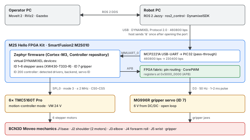
System components
| Component | Role | Platform |
|---|---|---|
| Operator PC | Motion planning, visualization and simulation (MoveIt 2, RViz2, Gazebo) | ROS 2, DDS client of the Robot PC |
| Robot PC | Robot-side ROS 2 control: ros2_control, the ROBOTIS hardware interface and DynamixelSDK; owns the USB link to the controller |
Ubuntu 24.04, ROS 2 Jazzy in Docker |
| Controller firmware | DYNAMIXEL Protocol 2.0 device: six stepper axes (IDs 1–6), the gripper servo (ID 7) and a controller device (ID 200) | Zephyr RTOS on the SmartFusion2 Cortex-M3 (M2S Hello FPGA Kit, M2S010) |
| FPGA design | Pin routing of SPI and UART, CorePWM for the gripper servo | SmartFusion2 FPGA fabric (Libero) |
| Drives | Six BIGTREETECH TMC5160T Pro modules in motion-controller mode, MG996R gripper servo | 24 V and 6 V supplies |
| Mechanics | Joints, links and printed parts | BCN3D Moveo |
Repositories
| Repository | Content |
|---|---|
| sfs-smartmanipulator-x-robot | Robot PC Docker image and ROS 2 workspace, the robot description generated from the Moveo CAD, diagnostics, and this documentation |
| sfs-smartmanipulator-x-operator | Operator PC: planning, visualization and simulation |
| sfs-smartmanipulator-x-skills | Engineering rules for coding agents, shared by all repositories of the project |
| SmartManipulator-X-Controller | Zephyr firmware for the SmartFusion2 and the host-side DYNAMIXEL motor tester GUI |
| SmartManipulator-X-Libero | FPGA design and the hardware contract for the firmware (docs/firmware_interface.md) |
Documentation map
| Section | Pages |
|---|---|
| Guide | Getting started: run the Robot PC in simulation and check it from a second host. Development: Docker, VS Code tasks, robot description, documentation, CI. |
| Robot PC | Robot PC: ROS 2 control, Docker, network, USB device. BCN3D Moveo mechanics: the mechanical source and the generated robot model. |
| System | System architecture: component boundaries, control path, ARM/FPGA partition, verified state. DYNAMIXEL compatibility: the shared host/device contract. Operator PC: planning, simulation, DDS. |
| Firmware | Getting started and development environment of the controller firmware. Firmware architecture: source layout, start-up order, threads, queues, data flow, configuration. Motor tester GUI: testing every axis and the gripper over DYNAMIXEL Protocol 2.0. |
| Hardware | Hello FPGA Kit wiring: the kit, the six TMC5160 modules, the servo and power. TMC5160 driver modules: pinout, motor connection, firmware interface review, bring-up checklist. Gripper servo (MG996R): supply, signal, bring-up and calibration. |
The whole documentation is also available as one PDF user manual (the PDF button in the header of the website).
Current status
- Robot PC: ROS 2 Jazzy Docker image with the selected ROBOTIS packages
and the project packages. In simulation (mock hardware) it runs
robot_state_publisher,ros2_controland the arm and gripper controllers on a Docker network that stands in for the Ethernet link; a smoke test from a second container checks discovery, the controllers and a trajectory. The robot description is generated from the BCN3D Moveo CAD; its joint limits are placeholders until measured on the arm. The real-hardwareros2_controlpath is not configured yet. - Controller firmware: builds in two variants, the target variant
(TMC5160 over SPI) and the simulation variant (simulated axes on the real
board, for protocol tests). Both implement a functional subset of a virtual
XW430-T333-R (PING, READ, WRITE, REG_WRITE, ACTION, SYNC_READ, SYNC_WRITE).
The simulation firmware passes the automated conformance check
(
firmware_check.py, 49/49, including the gripper servo) when it runs asnative_simon a PC. - Hardware (2026-10-11): the host link (460800 bps PC ↔ PIC32,
230400 bps PIC32 ↔ SmartFusion2) works on the kit. On axis A0 (BTT
TMC5160T Pro, 17HS19-2504S) SPI detection, the register mapping, telemetry,
Current Limit and the ramp generator are verified, but the shaft does not
turn yet: the module reads
SD_MODE=1(STEP/DIR mode) instead of the motion-controller mode, see finding 10 in Firmware interface review. Motor currents, ramps and the motor-to-axis assignment are described in Motor profiles and axis assignment. - Gripper servo: a virtual DYNAMIXEL device on ID 7 driven by CorePWM in the FPGA fabric. On the kit it follows Goal Position; its travel is not calibrated yet.
- Open items for the whole arm: verification of the upstream Jazzy sources against the device behavior (model numbers, registers), joint-to-motor mapping and gear ratios on the real arm, shoulder pairing (IDs 2 and 3), joint limits, and safety (emergency stop). The verified state versus target table tracks them.