Hardware and bring-up
Doppelstep runs on the STMicroelectronics B-G431B-ESC1 Discovery kit, a small electronic speed controller (ESC) board for drone motors, with a detachable debugger. This page describes the board, how the stepper motor is wired to it, how the firmware scales the measurements, and the steps to bring a new setup up safely.
The board
| Part | Detail |
|---|---|
| Microcontroller | STM32G431CBU6: Arm Cortex-M4F, 170 MHz, 128 KiB flash, 32 KiB SRAM |
| Power stage | L6387 gate drivers, STL180N6F7 MOSFETs, three half-bridges (legs U, V, W) |
| Current sensing | Three 3 mΩ low-side shunts, amplified by the internal OPAMPs of the MCU |
| Debugger | ST-LINK/V2-1 on a detachable part of the board, with a Virtual COM Port |
| Pinout | UM2516 Rev 4, Table 4 (boards/st/b_g431b_esc1/doc/index.rst) |
The board definition is part of this repository (boards/st/b_g431b_esc1/), because Zephyr
4.5 does not include it: 170 MHz from the 8 MHz crystal, the pinout of the user manual, and
the flash runners OpenOCD (default), J-Link, STM32CubeProgrammer and pyOCD.
Motor wiring
The board has three half-bridges, while a two-phase stepper has two coils. Doppelstep uses the shared-leg topology of Stepper-C: each coil sits between its own leg and the common leg W.
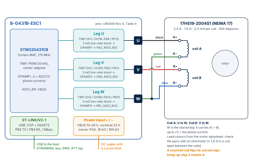
| Motor lead (17HS19-2004S1) | Coil end | ESC1 output | Leg pins (TIM1) | Current sense |
|---|---|---|---|---|
| Black | A+ | U | CH1 / CH1N: PA8 / PC13 | OPAMP1 → PA2 (ADC1_IN3) |
| Green | A− | W | CH3 / CH3N: PA10 / PB15 | OPAMP3 → PB1 (ADC1_IN12) |
| Red | B+ | V | CH2 / CH2N: PA9 / PA12 | OPAMP2 → PA6 (ADC2_IN3) |
| Blue | B− | W | CH3 / CH3N: PA10 / PB15 | OPAMP3 → PB1 (ADC1_IN12) |
The lead colours are those of the motor datasheet. Other motors, and some batches, use other colours: identify the two coils with an ohmmeter before connecting (about 1.6 Ω within a coil, open between the coils). Swapping the two ends of one coil reverses the sign of its current; bring-up step 3 checks it.
W carries the sum of both coil currents, iA + iB, up to √2 times the phase current. The
firmware measures its shunt too and switches the outputs off when |iW| exceeds the trip
current (aux-trip of the motor node).
The supply goes to the power input pads of the board (+ and −). The firmware accepts
10–28 V (vbus-min-mv, vbus-max-mv) and is tuned for 24 V; use a laboratory supply with a
current limit for the first runs. The USB cable to the ST-LINK carries the DYNAMIXEL bus, the
debugger and the RTT log.
The tested motor is a 17HS19-2004S1 (NEMA 17, 2.0 A rated, 1.6 Ω and 3.0 mH per coil, 200 steps per revolution). Another motor needs its values in the motor node (Configuration).
Current and voltage scaling
The scaling comes from the power stage node of the devicetree
(app/boards/b_g431b_esc1.overlay):
| Quantity | Value |
|---|---|
| Shunt | 3 mΩ |
| Amplifier gain | −64/7 ≈ −9.14 (OPAMP PGA 16 with VINM0 as the bias input, as in ST MCSDK, NuttX and SimpleFOC) |
| Current full scale | ±60.2 A with a 3.3 V reference, about 29 mA per ADC count |
| VBUS divider | 18 kΩ / (18 kΩ + 169 kΩ) |
| VBUS full scale | 34.3 V |
The DYNAMIXEL bus
The bus is USART2 (PB3 TX, PB4 RX), for now through the ST-LINK Virtual COM Port of the
debugger, at 1 Mbps. A DYNAMIXEL X430-T has no direction pin either: for a TTL half-duplex
bus later, USART2 can run in single-wire mode (single-wire; on &usart2, TX pin only).
Because USART2 carries the bus, the console and the log use SEGGER RTT through the debug
probe.
Bring-up checklist
Follow these steps in order on a new board or after a change to the power stage. They follow the integration guide of Stepper-C.
- Dead time (required). Enter the value of the B-G431B-ESC1 MCSDK (Motor Control
Workbench) project in
dead-time-nsofapp/boards/b_g431b_esc1.overlay. While it is 0 the firmware runs, but never enables the gate drivers: Torque Enable answers Result Fail and the log says "enable refused". Check the gate driver input polarity (TIM1 CHx/CHxN active high) against the same project. - Outputs off. The RTT log shows the current offsets (about 2048 counts) and the ADC readings. Compare Present Input Voltage with a multimeter.
- Polarity. Set
voltage-drive;and a lowrun-current-milliampin the motor node. After Torque Enable the measured phase A current must be positive. If not, setcurrent-sense-invert;in the power stage node. - Current loop. Back to current drive with a low run current: check that the current settles at the run current.
- Motion. Small Goal Position steps (DYNAMIXEL Wizard or the GUI), then the OpenMANIPULATOR-X profile.
- Protection. Lower
trip-current-milliampandvbus-max-mv, then check the trips and the Hardware Error Status.
After a change to the drivers or the threads, also run the hardware checklist: it covers what the PC tests cannot see.