Protection
Doppelstep protects the power stage and the motor in layers, from comparators that switch the gates off in hardware to checks before the torque comes on. Each layer covers what the one above cannot see or cannot do fast enough. This page lists them, with what each one detects, how fast it acts, what it does and how the host sees it.
The values are those of the B-G431B-ESC1 with the 17HS19-2004S1
(app/boards/b_g431b_esc1.overlay).
Overview
| Layer | Detects | Reaction time | Reaction | Hardware Error Status |
|---|---|---|---|---|
| Hardware comparators (STM32 backend) | Leg current above 10 A in a low-side switch; bus above 30 V | Break filter, about 0.5 µs | TIM1 break: gates off without software, latched until reset | Electrical Shock (0x10); Input Voltage (0x01) |
| Leg trip (STM32 backend, interrupt) | |iU|, |iV| or |iW| above 3.5 A, in current and voltage drive | Next PWM period, at most 50 µs | Outputs off, fault latched | Electrical Shock (0x10) |
| Fast-loop overrun (STM32 backend) | The fast loop did not finish within its period | One period | Outputs off in the interrupt, fault latched | Electrical Shock (0x10) |
| Stepper-C fast loop | Phase current or the current of the shared leg (|iA + iB|) above 3.5 A (current drive); bus below 10 V or above 28 V | Same period | Outputs off, fault latched | Electrical Shock (0x10); Input Voltage (0x01) |
| Stepper-C stall detection | The rotor does not follow the commanded angle | stall_time_ms |
Outputs off, fault latched | Not enabled in Doppelstep |
| Current offset check (calibration at start) | An offset outside 2300..2800 counts | Once, at start | Outputs refused for good, the bus keeps running | Electrical Shock (0x10) |
| Bus voltage check (Torque Enable, Stepper-C) | Bus outside 10..28 V | Before anything is energised | Torque Enable answers Result Fail, nothing latched | Input Voltage (0x01) |
| Self-test (first Torque Enable, Stepper-C and the motor driver) | Open coil, short, wrong polarity, coil on the wrong legs, broken current sensing, a leaking switch | About 15 to 60 ms, before the motor runs | Torque Enable is answered at once; on a failure the torque goes off again, fault latched | Electrical Shock (0x10) |
| Temperature (application) | NTC above Temperature Limit (80 °C), or the NTC open or shorted | With the live registers | Torque off until a Reboot (factory Shutdown mask) | Overheating (0x04) |
| Watchdog (application) | A task stops checking in | 500 ms | MCU reset: the outputs start off | None (the reset cause is logged) |
A latched fault keeps the outputs off: Torque Enable answers Result Fail until a DYNAMIXEL Reboot (an MCU reset on the board) clears it, as on an XM430.
Hardware trips
The software layers react at the PWM rate at best: 50 µs. A short through a switch reaches tens of amperes in a few microseconds, so the STM32 backend adds comparators that act without software.
Where the comparators look
The current amplifiers of the board are the internal OPAMPs of the MCU. Their non-inverting inputs (PA1, PA7, PB0) carry the shunt voltage on a bias set by the board:
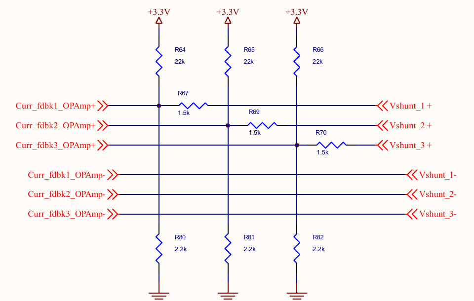
The node is a divider of three conductances, 1/22 kΩ to 3.3 V, 1/2.2 kΩ to ground and 1/1.5 kΩ to the shunt:
V+ = 3.3 V × (1/22k) / (1/22k + 1/2.2k + 1/1.5k) + Vshunt × (1/1.5k) / (1/22k + 1/2.2k + 1/1.5k)
   = 0.129 V + 4/7 × Vshunt
With the PGA gain of 16 this gives the −64/7 of the overlay, and the offsets measured on the board, about 2530 counts, are 16 × 0.129 V. One ampere through a 3 mΩ shunt moves V+ by 4/7 × 3 mV = 1.71 mV.
COMP1, COMP2 and COMP4 compare PA1, PA7 and PB0 with DAC3. The DAC level is computed after the
offset calibration from the measured offset: (offset + trip counts) / 16, so the spread of
the bias resistors and of the 3.3 V cancels. At 10 A and an offset of 2534 counts the level is
DAC code 180 (0.145 V). COMP3 compares the bus divider on PA0 with DAC1: 30 V is code 3583.
COMP1/2/4 drive the break input BRK of TIM1 and COMP3 drives BRK2, so the firmware can tell
the overcurrent from the overvoltage. The break clears MOE: every gate driver input goes low,
both switches of every leg are off. The interrupt then reports the trip
(POWER_STAGE_TRIP_HW_OC or _HW_OV) to the motor driver, which latches the fault. The backend
refuses its outputs after a break until the next reset.
What they catch, and what not
A current down through a low-side switch makes the shunt voltage positive: shoot-through, a phase shorted to the bus, a short between two phases while one of them is on its low side. The comparators catch all of these.
Limits
- A phase shorted to ground while its high side conducts does not pass any shunt. Only the undervoltage trip (if the supply collapses) and the current limit of the supply act. Use a laboratory supply with a current limit for the first runs.
- Comparator offset: up to ±5 mV in the datasheet, ±3 A at the trip level. 10 A stays well above the 3.5 A software trip and far below what the MOSFETs and shunts take. A setting near the bias does not work: 1 A tripped at rest on the test board.
- Break filter: 0.47 µs (fDTS / 16, N = 5) rejects switching spikes: no false break in 2 minutes of 180° moves at 46 rpm and 1.5 A on the test board.
Measured on the test board (outputs off, DAC3 swept with the debugger): COMP1 (U) and COMP2 (V) switch at DAC code 159, COMP4 (W) at 161, while the ADC offsets give 158.4 and 157.9. With the level of 10 A (code 180) the break therefore acts at about 9.9 A on U and V and 8.9 A on W. The overvoltage path was checked with a level of 11 V on a 12 V supply: Input Voltage Error right after the start, Torque Enable refused.
The simulated-motor build on the board leaves the comparators out (app/sim.overlay): its
outputs stay off, and the image has no flash to spare.
Software trips
Leg trip. The STM32 interrupt checks the current of every leg against the trip current of
the motor node (trip-current-milliamp, 3.5 A) in every PWM period. Stepper-C checks the two
phase currents itself, but only in current drive; the leg trip also covers voltage drive
(bring-up step 3, voltage-drive;) and the shared leg W, which carries iA + iB, up to √2 times
the phase current. It is active only after a successful offset calibration: with an unknown
offset a false trip would latch at every start.
Fast-loop overrun. When the next measurement is ready before the fast loop returns, the interrupt switches the outputs off at once and reports the overrun with the next sample (Architecture).
Stepper-C (fast loop, every 50 µs) trips on the phase currents and on the current of the
shared leg, |iA + iB|, in current drive, and on the bus voltage below vbus-min-mv (10 V) or above vbus-max-mv (28 V). Each check uses one sample, so the samples must be clean: the
sampling window keeps every switching edge out of them. Its stall detection
(stall_time_ms) is off in Doppelstep: the motor node has no stall properties yet.
Checks before the torque comes on
Current offsets. At start, with the outputs off, the backend measures the zero of every
current amplifier. An offset outside current-offset-min-counts..current-offset-max-counts
(2300..2800) means a broken amplifier, shunt or bias network. The stage then refuses its
outputs; the bus keeps running and Hardware Error Status shows Electrical Shock, so the host
sees the fault instead of a silent board. The RTT log names the offsets.
Bus voltage. Torque Enable with the bus outside 10..28 V answers Result Fail and raises
Input Voltage Error before anything is energised: sstep_enable() and sstep_selftest() of
Stepper-C check the last sample and answer SSTEP_ERR_VBUS, which the motor driver returns as
-ERANGE. Nothing is latched: once
the supply is in range, Torque Enable works (Hardware Error Status keeps the bit until a
Reboot, as on an XM430). With only the USB cable connected the bus reads about 4.7 V.
Self-test of the bridge and the motor
At the first Torque Enable after start or Reboot, the motor driver runs the self-test of
Stepper-C, sstep_selftest(), before Stepper-C takes over (CONFIG_SSTEP_MOTOR_SELFTEST, which
selects CONFIG_SSTEP_SELFTEST, the library option SSTEP_CFG_SELFTEST). The fast loop of the
library runs it, one step per PWM period:
- All legs low, 2 ms. No phase may carry current. A current here means a high-side switch that conducts.
- Coil A. W and V stay low, the duty of U rises slowly until the phase A current reaches
the test current (
selftest-current-milliamp, 600 mA), then holds it. - Coil B. The same with V.
Stepper-C sees the two phase currents only. Meanwhile the motor driver adds up the three leg currents of every sample, iU + iV + iW, which must be 0. Above a quarter of the test current for 2 ms in a row (40 PWM periods), the shunt or the amplifier of a leg is broken, and the test fails although Stepper-C passed it. A broken sensor is wrong for as long as current flows; single samples are not: in 15 tests on the board the sum reached 6 to 8 counts (once 25, a disturbed sample) against the limit of 5, for at most 2 periods in a row. The algorithm and its limits are in the Protection chapter of Stepper-C.
The voltage is ramped instead of set from the coil resistance: at 12 V the dead time of 1.2 µs eats about 0.58 V of the coil voltage, as much as the 0.96 V that 600 mA needs through 1.6 Ω. The levels of the checks include that loss.
| Log message | Likely cause |
|---|---|
no current (phase open, motor not connected or leg dead) |
Coil wire loose or not connected, motor unplugged, a switch or gate driver of the leg dead |
current too high (short circuit) |
Coil or phases shorted (the current came before the voltage could drive it through 1.6 Ω), or a trip during the test |
current of the wrong sign (current-sense-invert) |
The current sensing has the opposite sign: set or clear current-sense-invert; in the power stage node |
current in the other phase (phase on the wrong legs) |
A coil is connected to U and V instead of U and W (or V and W): check the wiring |
iU + iV + iW is not 0 (a current sensor is broken) |
Amplifier or shunt of a leg broken; the three leg currents must add up to zero |
current with all legs low (a switch conducts) |
A high-side switch conducts with its gate off |
aborted by a bus voltage trip or a power stage error |
The supply collapsed during the test (current limit too low) or the stage refused a command |
timeout |
The test did not end within 500 ms: the fast loop does not run |
The log line also gives the phase, its current, the compare value and the sum of the leg currents against the test current, both in ADC counts:
<err> sstep_motor: selftest: <cause>, phase <A|B>, <current> mA at duty <compare>, legs sum <counts> counts (test <counts>)
Torque Enable does not wait for the test, just as an XM430 answers Torque Enable at once:
DynamixelSDK, and with it the ROS 2 dynamixel_hardware_interface, waits only about 34 ms
for a status packet. The motor driver checks the bus voltage, starts the test and answers;
Torque Enable then reads 1, and the slow loop enables Stepper-C when the test passes. A Goal
Position or Goal Velocity written meanwhile is executed then (the latest one). On the board
at 24 V, Torque Enable is answered in 2 ms, and a Goal Position sent 2 ms later moves the
motor when the test has passed.
A failed test turns the torque off again, as a shutdown error of an XM430 does: Torque Enable reads 0, Hardware Error Status shows Electrical Shock, and the fault stays latched until a Reboot, so the test does not drive a broken bridge again and again.
During the test the rotor moves to the nearest full step of the energised coil, at most one full step (1.8°), and back when the motor is enabled. While it swings into the step it induces currents in both coils. Since Stepper-C 1.4.0 every check waits until the rotor is at rest: the hold ends when the other phase has stayed below half the own current for 2 ms in a row, the pause between the phases when both currents have stayed low for 5 ms, and twice the test current counts as a short only without a break for 100 ms. A wrong wiring or a short stays, so each check fails after 100 ms. On the motor model the test takes about 40 to 55 ms, also with a heavy load on the shaft. Stepper-C 1.3.0 judged a single sample: on the board, with the phases swapped and the rotor a full step away, it reported a coil on the wrong legs once.
The rotor must be at rest
A rotor turned by an external torque for longer than the checks wait, such as a loaded joint that falls, keeps inducing currents in the shorted coils, and the test reports a short, a leaking switch or a coil on the wrong legs. Support a joint under gravity load before the first Torque Enable.
The test runs once after a start; with CONFIG_SSTEP_MOTOR_SELFTEST_EVERY_ENABLE it runs at
every Torque Enable.
The self-test is off in the simulated-motor build on the board (flash) and on in native_sim,
where every SIL test runs it against the motor model.
Temperature and watchdog
Temperature. The NTC next to the bridge is converted in every PWM period. Above Temperature Limit (factory 80 °C) the firmware raises Overheating Error, which is in the factory Shutdown mask: the torque goes off and stays off until a Reboot. An open or shorted NTC trips the same way, because the stage is then not protected (Hardware).
Watchdog. The independent watchdog of the MCU resets it when the control or the communication task stops checking in for 500 ms. After the reset the outputs start off.
Where it is configured
| Setting | Node or option | Value on the B-G431B-ESC1 |
|---|---|---|
| Hardware overcurrent | hw-trip-current-milliamp (power stage) |
10000 |
| Hardware overvoltage | hw-trip-vbus-mv (power stage) |
30000 |
| Offset window | current-offset-min-counts, current-offset-max-counts (power stage) |
2300, 2800 |
| Software trip | trip-current-milliamp, aux-trip (motor) |
3500, on |
| Bus voltage | vbus-min-mv, vbus-max-mv (motor) |
10000, 28000 |
| Self-test current | selftest-current-milliamp (motor) |
600 |
| Self-test | CONFIG_SSTEP_MOTOR_SELFTEST, CONFIG_SSTEP_MOTOR_SELFTEST_EVERY_ENABLE |
y, n |
| Temperature Limit | Control Table address 31 | 80 °C |
| Watchdog | CONFIG_SFS_WATCHDOG_TIMEOUT_MS |
500 |
See Configuration for every property.
Checking it on the bench
The PC tests cover the logic: the trips, the fault mapping and every self-test result against a model. What they cannot check is the analog side: the comparator levels, the break filter and the self-test against the real motor. The hardware checklist has the steps.
On the B-G431B-ESC1 with the 17HS19-2004S1 at 24 V (2 A current limit), firmware 0.2.0 (all tests of the release: Test record):
| Scenario | Torque Enable | Result |
|---|---|---|
| No supply, USB only (4.7 V) | Result Fail in 2 ms | Input Voltage Error, nothing switched on |
| One coil disconnected | OK in 2 ms, then off | Electrical Shock, no current (phase open, …), phase A |
| No motor | OK in 2 ms, then off | Electrical Shock, no current (phase open, …), phase A |
| Coil A between U and V (check 27) | OK in 2 ms, then off | Electrical Shock, current in the other phase (phase on the wrong legs), phase A, 0.1 s after the start of the test |
| The two coils swapped, common wire on W | OK in 2 ms | Passes (the motor turns the other way: no encoder to see it); 5 of 5 with the rotor a full step away |
| Correct wiring, rotor a full step away | OK in 2 ms | Passes, 15 of 15 |
| Correct wiring: Goal Position 2 ms after Torque Enable, then the ros2_control loop at 100 Hz for 3 s | OK in 2 ms | The move runs after the test; 300 cycles, no failed Sync Read |